SIMPLE CIRCUITS


Throughout this lab, keep the circuit closed only long enough to, observe the necessary data.

Never connect the DMM in Current Mode in Parallel with any Resistor or Battery!

In this laboratory you will study simple circuits by measuring the current through and voltage across several circuits that consist of batteries and resistors.  Measurements will be made using a digital multi-meter (DMM).  As its name implies, it can measure voltage, current or resistance.  For the Tenma 72-1020 DMM, there are different connections to be made before making a measurement.  Incorrect connection in ohms or dc mA mode can cause a fuse to blow in the meter - which might end your experimentation for the day, so please be careful to be in the proper mode before making a measurement.

The wires for this laboratory have 'alligator clips' on the end that allow the circuits to be easily connected or disconnected.  To prevent discharging your batteries or excessive heat in the resistors, leave one of the clips disconnected until you are ready to perform a measurement.  If, at any time, you are in doubt, please ask your instructor.  The steps for obtaining your data, along with tasks and questions to be answered, follow.

  1. Set the Tenma 71-1020 DMM  to measure resistance using the ohms (W) mode as shown in the linked figure.  Then, measure the resistance of each of your three resistors using the DMM.
  2. Decide which resistor is to be R1, R2 and R3, and then use them as such throughout the lab.  The first data in your notebook should be a table listing the name of the resistor and its measured value.
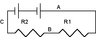
  3. Connect the circuit shown below - use wires for A, B and C. That way you can remove a wire to insert the ammeter when you want to measure the current through that wire. 
  4. Set the Tenma to measure DC milliAmperes as shown in the linked figure.
  5. Measure and record in a table the current at the points labeled A, B, and C.  (click for generic pictorials of how to measure the current at  points A and B.)  How would you expect the three values  to compare? Explain. 
  6. Set the Tenma to measure DC Volts as shown in the linked figure.
  7. Measure the potential difference across each resistor and then the potential across the two resistors together.
  8. Calculate the percentage difference between the sum of the individual voltage drops and that of the total.
  9. Show from the data. that the voltage is directly proportional to the resistance, when the current is constant. (i.e. compare V1 / V2 to R1/R2)

simplecir1.gif (2077 bytes)


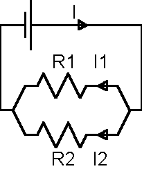
  1. Connect the circuit shown, below.
  2. Place the Tenma in current mode and measure the currents I, I1 and I2.
  3. Compare the total current, I, with the sum of I1 and I2.
  4. Show from the observed data that the two currents vary inversely with the corresponding resistances.
  5. Place the Tenma in voltage mode and measure the voltage across the battery and then measure the voltage across each resistor.
  6. How do the voltages compare?

simplecir2.gif (2641 bytes)


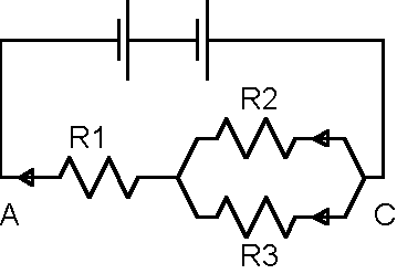
Connect the circuit shown below.

  1. Place the Tenma in voltage mode and measure the potential difference between points A and C.
  2. Using the voltage across A-C and the resistances R1, R2, and R3, calculate the current in each resistor.
  3. Place the Tenma in current mode and measure the three current values.
  4. Compare your calculated currents to your experimental currents.


simplecir4.gif (3312 bytes)


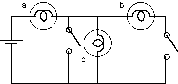
Using what you have now learned about series and parallel combinations of resistances predict the relative brightness of each of the bulbs in the circuit below. Assume all of the bulbs are identical. Explain your reasoning. Set up the circuit to check your predictions.  If you cannot see a glow from bulbs 'b' and 'c' try using two cells in series.
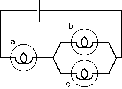
 

simplecir5.gif (3747 bytes)


For each of the circuits below, predict the brightness of each bulb, with the switches open, as shown. Then predict how each bulb will change in brightness when the switch is closed. Support your answers with explanations. Set up the circuit and check your predictions.  If you cannot see a glow from bulbs that you expect to glow, try using two cells in series.  If a lamp is overly bright, disconnect the battery quickly - before the lamp burns out.
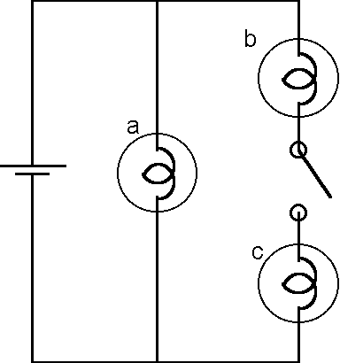
 

simplecir6.gif (4475 bytes)


simplecir7.gif (4402 bytes)


 last modified 2 April, 2018
Copyright B. E. Taylor