Uniform Circular Motion Lab
This experiment investigates how the force necessary to maintain a body in uniform circular motion (i.e. in a circle of constant radius and with a constant speed) is related to the speed of the object experiencing UCM. You should note that there are other possibilities for the independent variable. We are keeping all of the possible independent variables fixed save the applied force.

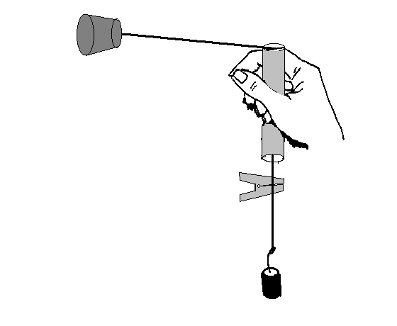
Your apparatus, shown in figure 1, consists of a glass tube, some string, a rubber stopper, and an alligator clip. The force that keeps the rubber stopper traveling in a circle at constant speed is supplied by the string. The source of the force is gravity pulling down on a mass attached to the lower end of the string. If we ignore the friction of the string on the glass tube, the force downward on the mass due to gravity is the same as the force inward on the stopper. Hence the force is Mhanging g and the velocity can be calculated by measuring the time for thirty complete circles, calculating the distance traveled (30 times the circumference), and then the average speed.
Before you begin your experiment, check your glass tube for chipped edges.
For each case, we know the radius of the circle is equal to the value set earlier, and that the applied force is the weight of the hanging mass. Calculate the force applied, and the resulting velocity for each case and complete a table like the one shown in your notebook.
Mhanging (kg) |
Time (s) |
v (m/s) |
Fhang (Nt.) |
Once your table is complete, plot a graph of velocity vs. applied force. What is the shape of the graph? If it is straight, draw in the best fit straight line and determine the equation for the best fit line. If the graph is not straight, use its shape to figure out how to re-plot the graph in such a manner as to obtain a straight (or straighter) line. Draw in the best fit line for this graph and determine the equation which describes the line.
Use Newton's second law (with the net force being the weight of the suspended mass) and your knowledge of circular motion to predict what the slope of your line should be. (i.e. solve for v in terms of Fnet. Calculate this theoretical slope. Compare this theoretical slope with the slope that you got from your best fit line. How well do they agree? Make a verbal comparison and also calculate the percentage difference between the experimental and theoretical slopes. Which slope is larger? What are some possible experimental reasons that the two might not agree? For one of the possible sources of errors (i.e experimental uncertainty not mistakes), think about whether it would tend to increase or to decrease the measured slope? Explain your reasoning.
Barney Taylor
Physics Dept.
Miami University - Hamilton
1601 University Blvd., Hamilton, OH 45011
(513) 785-3016
taylorbe@miamioh.edu
last modified Aug, 2013