The Magnetic Field in a Slinky
(Adapted from Physics with Vernier by Appel, Bakken, Gastineau, and Vernier.)
In this lab we will explore factors that affect the magnetic field inside the solenoid and study how the field varies in different parts of the solenoid. By inserting a Magnetic Field Sensor between the coils of the Slinky, you can measure the magnetic field inside the coil. You will also measure m0, the permeability constant. The permeability constant is a fundamental constant of physics.
Objectives
· Determine the relationship between magnetic field and the current in a solenoid.
· Determine the relationship between magnetic field and the number of turns per meter in a solenoid.
· Study how the field varies inside and outside a solenoid.
· Determine the value of m0, the permeability constant.
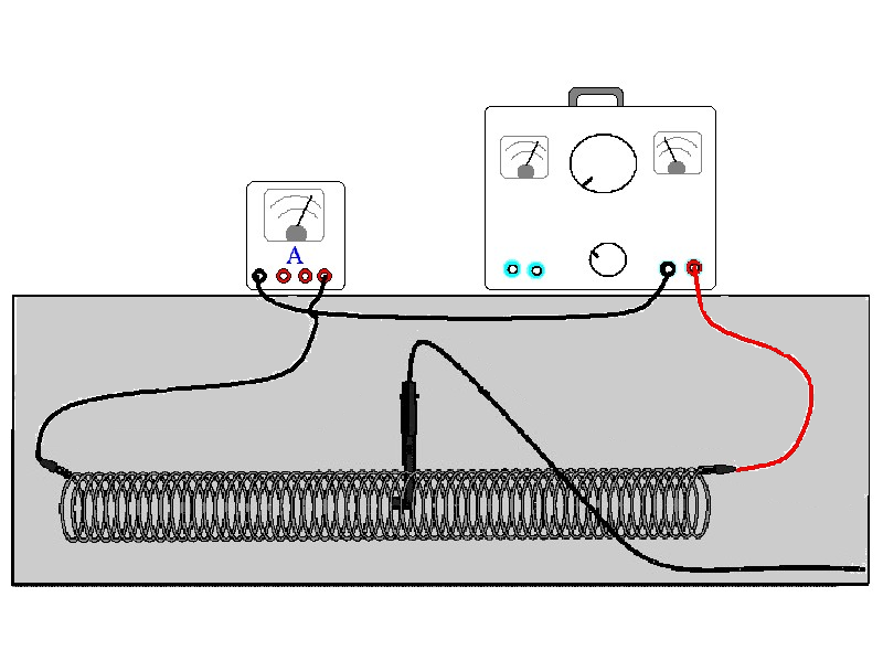
Figure 1
Initial setup
1. Connect the Vernier Magnetic Field Sensor to Channel 1 of the interface. Set the switch on the sensor to 0.3 mT (high amplification).
2. Stretch the Slinky until it is about 1 m long. The distance between the coils should be about 1 cm. Use a non-conducting material (tape, cardboard, etc.) to hold the Slinky at this length.
3. Set up the circuit and equipment as shown in Figure 1. Wires with clips on the end should be used to connect to the Slinky. If your power supply has an accurate internal ammeter, you do not need an additional external ammeter.
4. Open the file “Magnetic Field in Slinky” in the PHY 174 or PHY 184 folder. A graph will appear on the screen. The graph displays magnetic field in millitesla, mT. The graph is a live display of the magnetic field intensity.
Note: This
lab requires fairly large currents to flow through the wires and Slinky. Only allow the
current to flow when you are taking a measurement. The Slinky, wires, and possibly the
power supply may get hot if left on continuously.
Preliminary Explorations
1. With the Magnetic Field Sensor in position, but no current flowing, click ![]() to zero the sensor and remove
readings due to the Earth’s magnetic field and any magnetism in the metal of the
Slinky
to zero the sensor and remove
readings due to the Earth’s magnetic field and any magnetism in the metal of the
Slinky
2. Adjust the power supply so the current is 2.0 A. Place the Magnetic Field Sensor between the turns of the Slinky near its center. Slowly rotate the sensor and determine which direction gives the largest magnetic field reading. What direction is the white dot on the sensor pointing? Reference your direction as 'toward the negative clip' or 'toward the positive clip'.
3. What happens if you rotate the white dot to point the opposite way? What happens if you rotate the white dot so it points perpendicular to the axis of the solenoid?
4. Stick the Magnetic Field Sensor through different locations along the Slinky to explore how the field varies along the length. Always orient the sensor to read the maximum magnetic field at that point along the Slinky. How does the magnetic field inside the solenoid seem to vary along its length?
5. Check the magnetic field intensity just outside the solenoid. Check different distances from the slinky and different orientations of the probe.
Procedure
Part I How Is The Magnetic Field In A Solenoid Related To The Current?
For the first part of the experiment you will determine the relationship between the magnetic field at the center of a solenoid and the current flowing through the solenoid. As before, turn the current off except when making a measurement.
-
Set the current to 1.0 A Place the Magnetic Field Sensor between the turns of the Slinky near its center. Rotate the sensor so that the white dot points directly down the long axis of the solenoid and gives a positive reading. This will be the position for all of the magnetic field measurements for the rest of this portion. Turn the current off.
-
Adjust the power supply to a current of 1.0 A.
-
With the Magnetic Field Sensor in position, but no current flowing, click
 to zero the sensor and remove
readings due to the Earth’s magnetic field and any magnetism in the metal of the Slinky. Since the
Slinky is made of an iron alloy, it can be magnetized itself. Moving the Slinky around can cause a change in the field,
even if no current is flowing. This means you will need to zero the reading each time you
move or adjust the Slinky.
to zero the sensor and remove
readings due to the Earth’s magnetic field and any magnetism in the metal of the Slinky. Since the
Slinky is made of an iron alloy, it can be magnetized itself. Moving the Slinky around can cause a change in the field,
even if no current is flowing. This means you will need to zero the reading each time you
move or adjust the Slinky. -
Click
 to begin data collection.
Collect data for at least 10 seconds.
Turn the
current down to zero when you are done.
to begin data collection.
Collect data for at least 10 seconds.
Turn the
current down to zero when you are done. -
View the field vs. time graph and determine the region of the curve where the field was nearly constant. Select this region on the graph by dragging over it. Determine the average field strength by clicking the Statistics button. Record the average field in a data table.
-
Repeat steps Steps 2 - 5 while using currents of 1.5 A, 2.0 A, 2.5 A, 3.0 A and 3.5A in step 2.
-
Count the number of turns of the Slinky and measure its length between the two electrical connections. If you have any unstretched part of the Slinky at the ends, do not count it for either the turns or the length.
-
Record the length and turns, and then calculate and record the number of turns per meter.
-
On Page 2 of the experiment file, plot a graph of magnetic field B vs. the current I through the solenoid. How is magnetic field related to the current through the solenoid?
-
Determine the equation of the best-fit line, including the y-intercept. Note the constants and their units. Is the y-intercept what you would expect it to be? Turn off the 'connect-the-points" before printing your plot with the best-fit line.
Figure 2
Part II How is the Magnetic Field in a Solenoid Related to the Spacing of the Turns?
For the second part of the experiment, you will determine the relationship between the magnetic field in the center of a coil and the number of turns of wire per meter of the solenoid. You will keep the current and number of turns constant. You will be changing the length of the Slinky from 0.75 to 2.00 m to change the number of turns per meter.
-
Leave the Slinky set up as shown in Figure 1, but set the length between the electrical connections to 0.75 m.
-
The sensor will be oriented as it was before, so that it measures a positive field down the middle of the solenoid.
-
With the Magnetic Field Sensor in position, but no current flowing, click
to zero the sensor and remove
readings due to the Earth’s magnetic field and any magnetism in the metal of the Slinky. Since the
Slinky is made of an iron alloy, it can be magnetized itself. Moving the Slinky around can cause a change in the field,
even if no current is flowing. This means you will need to zero the reading each time you
move or adjust the Slinky. -
Click
to begin data collection. Adjust the power
supply so that the current is 2.5 A. Take data for at least ten seconds. Turn the current down to zero when you are done. -
Select a constant region on the graph by dragging over it. Find the average field while the current was on by clicking on the Statistics button.
-
Verity that the length of the slinky has not changed. Recount the number of turns of the Slinky if you think it has changed due to having a different unstretched portion at the end. If you have any unstretched part of the Slinky at the ends, do not count it for either the turns or the length. Record the length of the Slinky, the number of turns and the average field in a data table.
-
Repeat Steps 4-6 after changing the length of the Slinky to 0.75 m, 1.00 m, 1.25m, 1.50 m, 1.75 m, and 2.00 m. Each time, zero the Magnetic Field Sensor with the current off. Make sure that the current remains at 2.5 A each time you turn it on.
-
For each of the measurements of Part II, calculate the number of turns per meter. Enter these values in a data table.
-
On Page 3 of the experiment file, plot a graph of magnetic field B vs. the turns per meter of the solenoid (n).
-
How is magnetic field related to the turns/meter of the solenoid?
-
Determine the equation of the best-fit line to your graph. Note the constants and their units.
-
From Ampere’s law, it can be shown that the magnetic field B inside a long solenoid is B = m0nI where m0 is the permeability constant. Do your results agree with this equation? Explain.
-
Assuming the equation in the previous question applies for your solenoid, calculate the value of m0 using your graph of B vs. n.
-
Calculate the value of m0 using your graph of B vs. I as well. Do your two values agree?
-
Look up the value of m0, the permeability constant. Compare it to your experimental values.